Horizontal Directional Drilling (HDD)
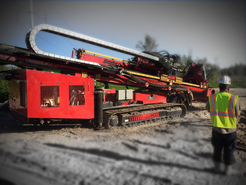
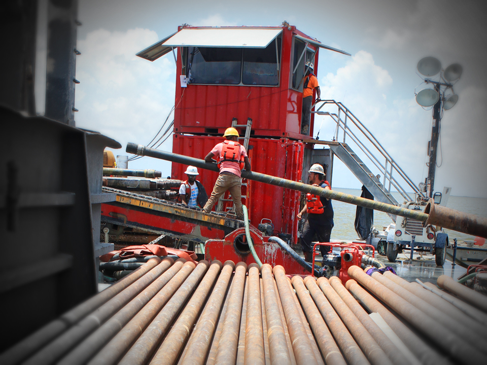
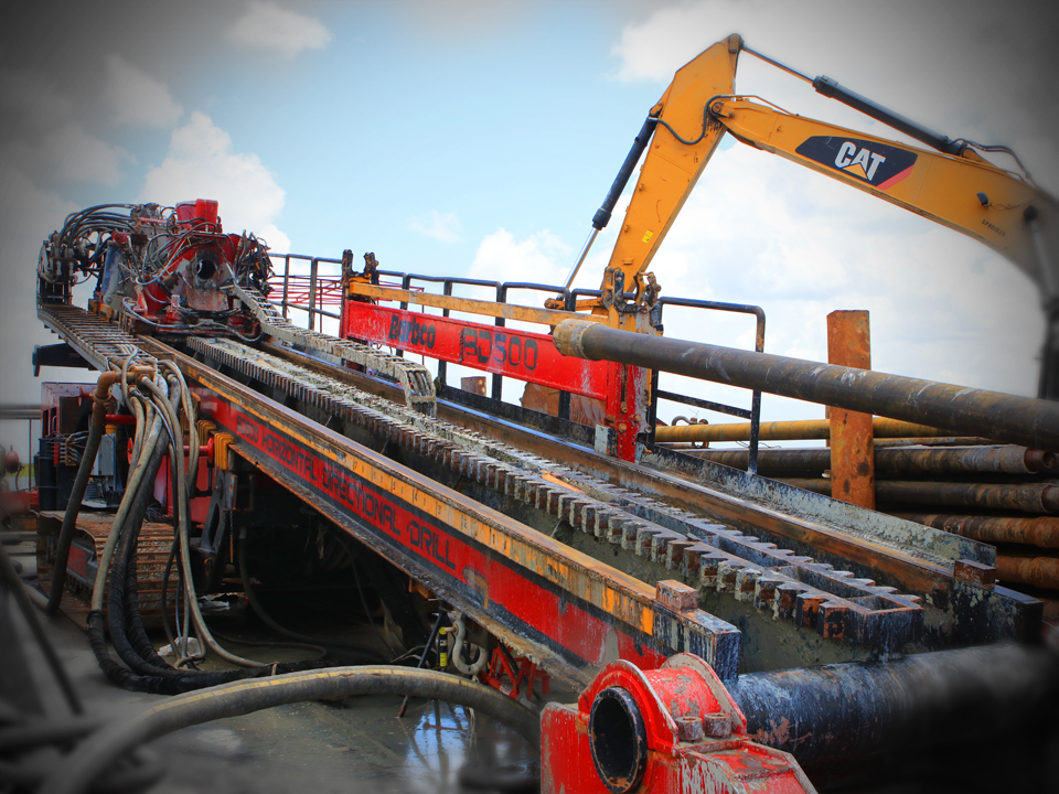
is a method of trenchless pipeline and utility installation requiring the use of either a “mini” or “maxi” surface launched drilling rig. Much like an Oilfield drilling rig, the drilling rig rotates and pushes drill pipe under the surface of the ground from an entry point to an exit point using a radius arc curve.
Once the pilot hole is completed the reaming process begins to increase the size of the bore hole to a size large enough to allow for the installation of the product pipe during the pullback process.
HDD has become a preferred choice of trenchless installation when minimal surface disturbance is required and offers many environmental advantages.
Road Boring
“Jack” and bore or “dry” bore are considered the same. This method of trenchless installation is most commonly selected when steel casings ranging from 12” to 84” are required at depths of less than 18’.
Both entry and exit pits would be required for placement of the machine and receiving the casing on the far side of the obstruction. Once the machine is placed in the entry pit and set to the desired grade, the casing (20’) is placed on the machine with an auger inside and the “jacking” begins.
This process is repeated 20’ at a time until the casing reaches the receiving or exit pit.

Direct Pipe
is the latest most advanced form of trenchless installation of pipe diameters above 24”. Expanding on micro tunneling length limits, this method now pushes farther. Direct pipe, as the name implies, does just that. By installing hydraulic rams (thrusters) that clamp onto the pipe at entry point, the micro tunneling head and pipe are pushed forward 20’ at a time, as the cutting face makes the hole.
New limits are still being achieved. Currently the largest diameter is 56” and has reached 6,000’. Direct pipe also solves the ongoing problems of dealing with the void around the pipe and downhole pressure when using HDD. There is no need to increase the hole size by multiplying the diameter of the pipe by 1.5 for the purpose of transporting the cuttings with direct pipe. The slurry is transported internally, reducing external downhole pressure, through piping inside the product pipe, back to the entry point where solids control systems process the slurry for reuse, much like HDD.
In addition, the need for space on exit side is eliminated since no pull section is needed. All activities take place on entry side. Therefore, with one step, no overcut, minimal down hole pressure and little space required on exit side. Direct pipe solves most of the concerns for the trenchless installations thus far.
Micro Tunneling
is the technological progression of the jack & bore method. While jack & bores are usually bores under 300′ with diameters of 12″ up to 84″. The micro-tunnels can reach 1,000′ with diameters of 48″ up to 144″.
The casing joints are lowered in the pit or shaft one section at a time, as are the jack & bore’s. The steering head is controlled from the surface with umbilical lines lowered into the pit and through the pipe. The lines are for power, steering, and slurry (mud) lines. With this slurry system, there are no augers or spoil inside the pipe. The cutter/steering head is water tight, which allows a continual flow of drilling fluids (bentonite) to flow to the head and back to mixing systems to be filtered and strained, then reused.
This updated generation of boring allows us to bore under the water table unlike the open jack & bore method.

Tunneling
uses Tunnel Boring Machines (TBM’s) to excavate tunnels from 60” to 60’. There are many different types of TBM’s depending on the type of geologic conditions, tunnel design, construction plan and logistics.
TBM’s are built job specific usually upon gathering the information necessary and reviewing your project. We would welcome any questions in regards to assisting you with your project design and machine selection.
Hydro Excavation
is the process of removing or moving soil with pressurized water. An air conveyance or vacuum is then used to transfer the soil or debris to a debris tank. This allows for a non-destructive and more accurate way to excavate soil and locate underground utilities.
Hydro excavation avoids damage to underground pipes, lines and cables, eliminating the high expenses needed for repairs and restoration. Fewer repairs means less time to get the job done too.
Bulkhead Tiebacks
Utilizing HDD or trenchless methods to support an existing weak bulkhead is achieved when obstructions don’t provide the area needed for installing traditional tie backs.
HDD can be used to drill beneath nearby buildings/structures and provide support from further distances away from water’s edge.
Drilled Shafts
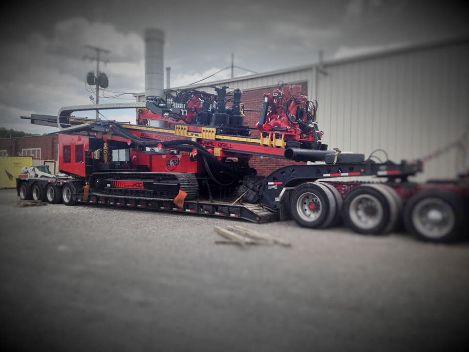
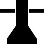
are deep foundation solutions used to support structures with large axial and lateral loads by excavating cylindrical shafts into the ground and filling them with concrete. They range in diameter from 24” to 120” and can be installed to depths in excess of 300 feet.
Drilled shafts are an economic solution that can be installed in a variety of different ground conditions where driving pilings would not provide a constructible method of installation.
Cathodic Protection
is a technique used to control the corrosion of a metal surface by making it the cathode of an electrochemical cell. A simple method of protection connects the metal to be protected to a more easily corroded “sacrificial metal” to act as the anode. The sacrificial metal then corrodes instead of the protected metal.
HDD again provides a simple solution to installing these Anode beds where protection is needed beneath existing structures or tanks.

Pressure Grouting
involves injecting a grout material into otherwise inaccessible, but interconnected pore or void space of which neither the configuration or volume are known.
The grout may be a cementitious, resinous, or solution chemical mixture. The greatest use of pressure grouting is to improve geomaterials (soil and rock). The purpose of grouting can be either to strengthen a formation or to reduce water flow through it. It is also used to correct faults in concrete and masonry structures.
Vertical Tunneling
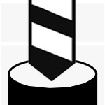
is a vertical shaft usually for the benefit of launching casing bores, micro tunnels, or tunnels at depths usually too great to work with conventional pit designs.
The walls of the round shaft provide the necessary strength to support the geologic forces at work with the extensive depths.
Machines like Vertical Tunnel Boring machines (TBM’s), Vertical Shaft Sinking machines (VSM’s) or Shaft Boring Machines (SBM’s) would be utilized for the construction and installation of the shaft.
No Project Too Big or Too Small for LaGreca
Whether your trenchless needs are on land or water, require pipe sizes from 1” to 120” or possibly lengths from 10’ to 7,000’, we have the equipment and personnel to meet your needs.
Don’t know what you need? Not a problem for us. LaGreca Services, Inc. has designed and built complete projects up to distances of 10 miles!
Contact us about your next project!

